What is this about?
Few weeks ago philixxx a friend was about to change the autopilot of his boat. Instead of going to a regular boat autopilot vendor, we have decided to make our own.
Few reasons to this:
- that’s fun
- not very complicated
- can be mostly made out of software – and we know of to deal with that
- can be easily extended to support more features – at a small time and money cost
Since this is our first autopilot, we will try to keep it simple. So essentially the first version will only have one feature: hold the current course. Once we have this, we can always add more features.
Boat autopilot principle
A boat autopilot is a closed-loop control system! Interestingly, PID controllers have been designed to steer ships in the 1890s.
Classical boat autopilot are based on gyro-compass and most of them rely on a rudder feedback. The gyro-compass provides the heading even when the boat is moving – roll and pitch. The rudder feedback gives the actual position of the rudder. And the autopilot actuates the rudder to a given position so that the boat goes in the right direction. But in order to make our system more reliable, we want to avoid the mechanical part as much as possible hence exit the gyro-compass and exit the rudder feedback.
To obtain the direction the boat is going, we use a GPS. This changes a bit the system. Instead of controlling the heading (angle between something fix and the direction of the boat), we control the course (angle between something fix and the tangent to the trajectory). This should make the system more robust to marin current though there will still some drift.
Another difference is that the GPS does not provide an accurate course unless we move. To make sure the movement is significant enough, we use a threshold on the speed and disable the autopilot when the speed is too low. Last word about the course, since we use a GPS, and not a magnetic compass, the reference is the geographical north. In the remaining, we mean true course when we mention the course. That’s it for the course.
As for the lack of rudder feedback, we will use a end to end control loop from the desired course to the measured course through the rotation of the steering wheel. In case there is an important hysteresis we are at risk of facing a control jumping from on extreme to the other. Fortunatly we don’t have much hysteresis in our system.
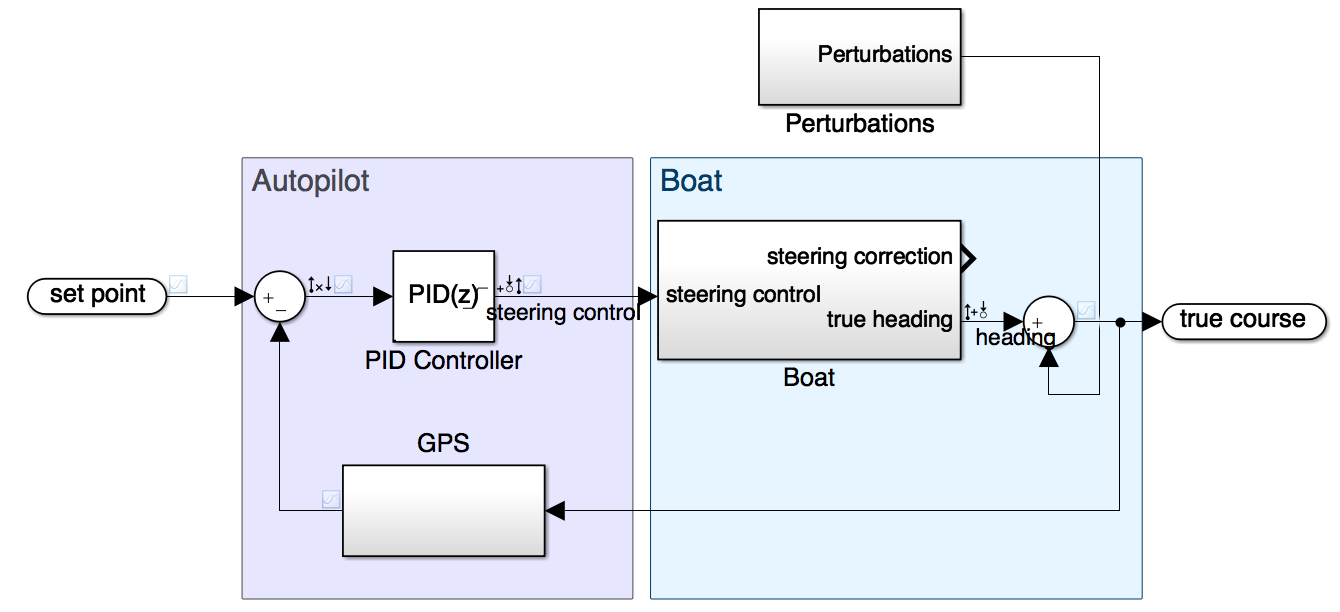
The overall principle is then to compare the target course (set point) with the actual course to define the error. The error enters the controller which determine the control to be applied. Then the mechanical part that rotate the steering wheel convert this into a steering correction which results in a boat heading. Depending on the current – or obstacles :) – as modeled in the perturbations, this will in turn become a course which will be sensed by the GPS and used for the error computation. We have a closed loop system. This slicing which hides how the control is transformed into a steering correction in the ‘boat’, will become more obvious when we will discuss the Tuning of this system.
Architecture
The architecture is more detailled in this document but we will highlight some part here.
We have built this autopilot as an embedded system around an Intel Edison board. This board offers a dual Atom with a Linux operating system plus plenty of IO pins – GPIO and PWM as we will detail later. This board is incredibly tiny but has a huge potential. Since it is a x86 running on Linux, it is very easy to develop for it and the integration effort is mininal – when you use an ARM or MIPS board, it is often quite difficult to find your favorite libraries or runtime environment. Here we are playing at home. The storage, usb serial console and onboard wifi make it really easy to use.
So, we distinguish two parts in our architecture: the Hardware and the Software. Let’s put aside the software architecture for some time and focus on the hardware.
Hardware
As already mentionned the system is built around an Intel Edison board. We use a serial interface GPS board from Adafruit for the GPS and a Big Easy Driver from Sparkfun to drive the stepper motor. The interfacing is achieved via a serial interface as for the GPS for example or via GPIOs (standard I/O or PWM). Some pins of the board have multiplexed I/O and PWM capabilities, using sysfs kernel interface of the embedded Linux you can select what you want the pin to be.
The user interface is made of 2 buttons, 5 LEDs and an alarm. First button is the master ON/OFF switch. Second button enable or disable the autopilot. LEDs are ON when the correspond error or warning conditions are met. If one error LED is ON while autopilot is enabled, the sound alarm is raised and the stepper motor is put to sleep (no holding torque) so someone can intervene. We have different error conditions: Absence of GPS fix, Invalid gps data, speed lower than minimum speed required to have a meaningful course, way too far from the desired direction and finally a warning which light when we are currently issuing the maximum permitted correction.
Everything is powered up from the 12V provided by the generator of the boat. We have also have a 3.3V and a 5V regulator to serve a reference tension for the level-shifter and to power the GPS and stepper motor driver board logic – the power for the coils comes from a fused 12V. The big easy driver as a current limiting feature which we set to about 0.7A as this provides enough torque for our case and is supposed to make the heat dissipator on the h-bridge unnecessary.
GPIO/PWM pin multiplexing on Intel Edison
We are using a mini breakout board for the Intel Edison. This has a limited number of pins. But some of them are multiplexed and via configuration we can decide which pin does what GPIO pin multiplexing guide.
For our design, we need:
- one serial interface for the GPS
- one PWM pin for the motor rotation
- one GPIO output pin for motor direction control
- one GPIO output pin for motor sleep state control
- one GPIO input pin for the hold course button
- five GPIO output pin to control status LEDs
- one GPIO output for the alarm
Currently, we use the following pins:
The LEDs of the dashboard use the following GPIOs – and their respective pin of the mini breakout header: - NoGPSFix: gpio40 → J19 - pin 10 - InvalidGPSData: gpio43 → J19 - pin 11 - SpeedTooLow: gpio48 → J19 - pin 6 - CourseErrorOutOfBounds: gpio82 → J19 - pin 13 - CorrectionAtLimit: gpio83 → J19 - pin 14
The alarm uses gpio183 (J18 - pin 8) – which is also pwm3.
For the motor, we use a Big Easy Driver from Sparkfun to drive the stepper motor. This requires the following pins to control, the direction, sleep state, and steps:
- motorDir: gpio165 → J18 - pin 2
- motorSleep: gpio12 → J18 - pin 7
- motorStep: gpio182 → J17 - pin 1 – which is pwm2
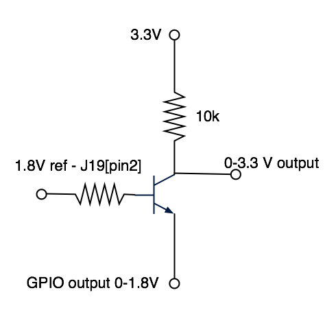
Because GPIO and PWM are only 1.8V, we need to level shift the IO to 3.3V to match the logic voltage of the stepper motor driver. We don’t want the input of the driver to be floating. For this, we use the following inverting circuit based on a 2N3904 NPN transistor:
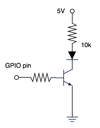
Pins driving the LEDs or the buzzer use a more standard NPN based-driver as shown on next figure.
Interface with the steering wheel
In our case, the stepper motor is physically interfaced with the steering wheel with a pulley/belt mechanism that has a reduction ratio of 15.2. The stepper motor is a 125 oz.in 200 step/rev NEMA 23 stepper motor. With the reduction ratio, the torque is enough to rotate the steering wheel. You can find stepper motors with pretty much any torque, it’s just a matter of price…
Now we need some code to tie all that together, that’s what next section is about.
Software
We have used Golang for this project because it is a modern language, very well suited for low level things, and with a great support for cross-platform compilation. It is very easy to built Linux x86 binary for your x86-64 Mac laptop, just have to set the following env variables: GOARCH=386 GOOS=linux.
In addition the go routine and go channel make it very easy to built a multi-component architecture with each component running its own event loop and communicating with the other via message exchanges.
Software Architecture
The software is architectured around 6 components:
- gps – which streams the position, course, speed and signal quality
- control – which collects user inputs
- pilot – which determine the course error and control to apply to the steering
- steering – which controls the steering of the boat
- dashboard – which display notifications
- alarm – which controls the alarm
Each component as a single event loop implemented as a go routine.
It reads on the input channels, does what it has to do and send messages to another component. Components are created, wired, started and shutdown in cmd/edisonIsThePilot.go.
As an example, this is the event loop of the alarm component:
type alarmUpdateActionMessage struct {
  alarm bool
}

// Start the event loop of the Alarm component
func (d *Alarm) Start() {
  go func() {
    defer func() {
      if r := recover(); r != nil {
        d.panicChan <- r
      }
    }()

    for {
      select {
      case m := <-d.inputChan:
        switch m := m.(type) {
        case alarmUpdateActionMessage:
          d.processMessage(m)
        }
      case <-d.shutdownChan:
        d.shutdown()
        return
      }
    }
  }()
}
An action from another component on this one only consist of creating a message with the right type alarmUpdateActionMessage here and posting it on the inputChan. This does not require any locking. Note the message type is opaque (lower case thus not exported) and need to be created with the NewAlarmUpdateActionMessage(...) function which do not leak the type:
// NewAlarmUpdateActionMessage creates a new alarm state update message
func NewAlarmUpdateActionMessage(alarm bool) interface{} {
  return newAlarmUpdateActionMessage{alarm: alarm}
}
In the event the action should return something, the type corresponding to this action also contains a channel on which the caller will listen to and the callee will send the value to be returned.
In case of a panic somewhere in the code, the recover() catch it and send the error on the panicChan, the main program has a go routine which listen to this channel and set the alarm, stop the motor then exits when it has a message.
go func() {
    select {
    case m := <-panicChan:

      // kill the process (via log.Fatal) in case we can't create the PWM
      if pwm, err := pwm.New(conf.AlarmGpioPWM, conf.AlarmGpioPin); err == nil {
        if !pwm.IsExported() {
          err = pwm.Export()
          if err != nil {
            log.Error("Failed to raise the alarm")
          }
        }

        pwm.Enable()
      } else {
        log.Error("Failed to raise the alarm")
      }
      // The motor
      motor := motor.New(
        conf.MotorStepPin,
        conf.MotorStepPwm,
        conf.MotorDirPin,
        conf.MotorSleepPin)
      if err := motor.Disable(); err != nil {
        log.Error("Failed to stop the motor")
      }
      motor.Unexport()

      log.Fatalf("Version %v -- Received a panic error -- exiting: %v", Version, m)
    }
  }()
conf/conf.go contains the pin mapping and definition of constants.
drivers folder contains the drivers for the I/O subsystem used in this project: gpio, pwm, stepper motor, serial-attached gps.
Interfacing with the GPS
This GPS provides a serial NMEA interface. We are interested in the following sentences:
The GPRMC sentence will be used:
$GPRMC,hhmmss.ss,A,llll.ll,a,yyyyy.yy,a,x.x,x.x,ddmmyy,x.x,a*hh
1    = UTC of position fix
2    = Data status (V=navigation receiver warning)
3    = Latitude of fix
4    = N or S
5    = Longitude of fix
6    = E or W
7    = Speed over ground in knots
8    = Track made good in degrees True
9    = UT date
10   = Magnetic variation degrees (Easterly var. subtracts from true course)
11   = E or W
12   = Checksum
As well as the GPGGA:
$GPGGA,hhmmss.ss,llll.ll,a,yyyyy.yy,a,x,xx,x.x,x.x,M,x.x,M,x.x,xxxx*hh
1    = UTC of Position
2    = Latitude
3    = N or S
4    = Longitude
5    = E or W
6    = GPS quality indicator (0=invalid; 1=GPS fix; 2=Diff. GPS fix)
7    = Number of satellites in use [not those in view]
8    = Horizontal dilution of position
9    = Antenna altitude above/below mean sea level (geoid)
10   = Meters  (Antenna height unit)
11   = Geoidal separation (Diff. between WGS-84 earth ellipsoid and
       mean sea level.  -=geoid is below WGS-84 ellipsoid)
12   = Meters  (Units of geoidal separation)
13   = Age in seconds since last update from diff. reference station
14   = Diff. reference station ID#
15   = Checksum
First is used for the course and speed, second is used for the fix quality (field #6). This interface is attached to one of the serial interfaces of the Edison.
We use adrianmo/go-nmea library to decode the messages and use tarm/serial to access the serial interface. The serial interface is /dev/ttyMFD1.
PID controller
This is the heart of the autopilot.
The input of the PID is the error defined as the difference between the current course as provided by the GPS and the reference course we have saved right after the autopilot has been enabled. The error is centered on 0 and varies from -180 (excluded) to 180 (included). The output of the PID is fed to the steering module which interpret this as the rotation to be done in one direction or the other.
We use our own implementation of a PID with filtered derivative:
func (p *PID) updateWithDuration(input float64, timeDifference float64) float64 {

  // error
  u := p.setPoint - input

  // output computation
  filterCoefficient := (p.kd*u - p.filterState) * p.n
  output := (p.kp*u + p.integratorState) + filterCoefficient

  if timeDifference > 0 {
    p.integratorState += p.ki * u * timeDifference
    p.filterState += timeDifference * filterCoefficient
  }

  // saturation
  if output > p.maxOutput {
    p.integratorState -= output - p.maxOutput
    output = p.maxOutput
  } else if output < p.minOutput {
    p.integratorState += p.minOutput - output
    output = p.minOutput
  }

  return output
}
In our case, the output of the PID is used to control the stepper motor which through the steering wheel and the boat itself, will correct the course.
Interfacing with the stepper motor
We control the stepper motor at a fixed speed. We do so to avoid excessive vibrations that occure at low speed and better control the torque of the motor. This means that to make it move of specific angle – or number of steps –, we need to control the time during which it is rotating.
Since we use a PWM (Pulse Width Modulation) pin from the Edison, we essentially have to:
- set the period of the PWM to the desired value – from the desired speed –,
- enable the output,
- wait for a certain amount of time
- and disable the output.
From the tests we have done, this can introduce a small error that we have measured to be less than 1%. Since this error is inside the control loop, it is similar to any perturbation the system can have to face – marin current, wind, … – which the overall system is designed to compensate for.
OS integration
Let’s finish this section with a bit of practical consideration on how we get this program runs on the Edison.
Since we use go, we get a statically-linked executable file which is very convenient to deploy on the board. We have added the ability to configure some parameters of the program via a config file in/etc/. So we have only two files to deploy to be able to run the autopilot.
Though that enough to run the program, we will complexify a bit the setup to have the autopilot autostarts at boot and clean the LEDs state when the autopilot program is not running.
The Edison is running a Linux distro with systemd. We take advantage of that and start our program as a service with pre and post execution commands to light all the LEDs so we see when the autopilot program is not running.
When the autopilot exits on an error condition, the alarm is raised. In case the autopilot program is started and the hold course button is ON, the alarm is raised until the button is switched OFF.
At boot the alarm is ON until the edisonIsThePilot is started – this is actually a side effect of the initial state of the GPIO pin but this is quite convenient for us.
Log rotation
The autopilog program generates log entries to record the various error conditions or state changes it observes. Because of the integration with systemd, logs are managed by journalctl. We have configured it to limit the maximum amount of logs kept.
Logs can be watched with:
# journalctl -u edisonIsThePilotMore
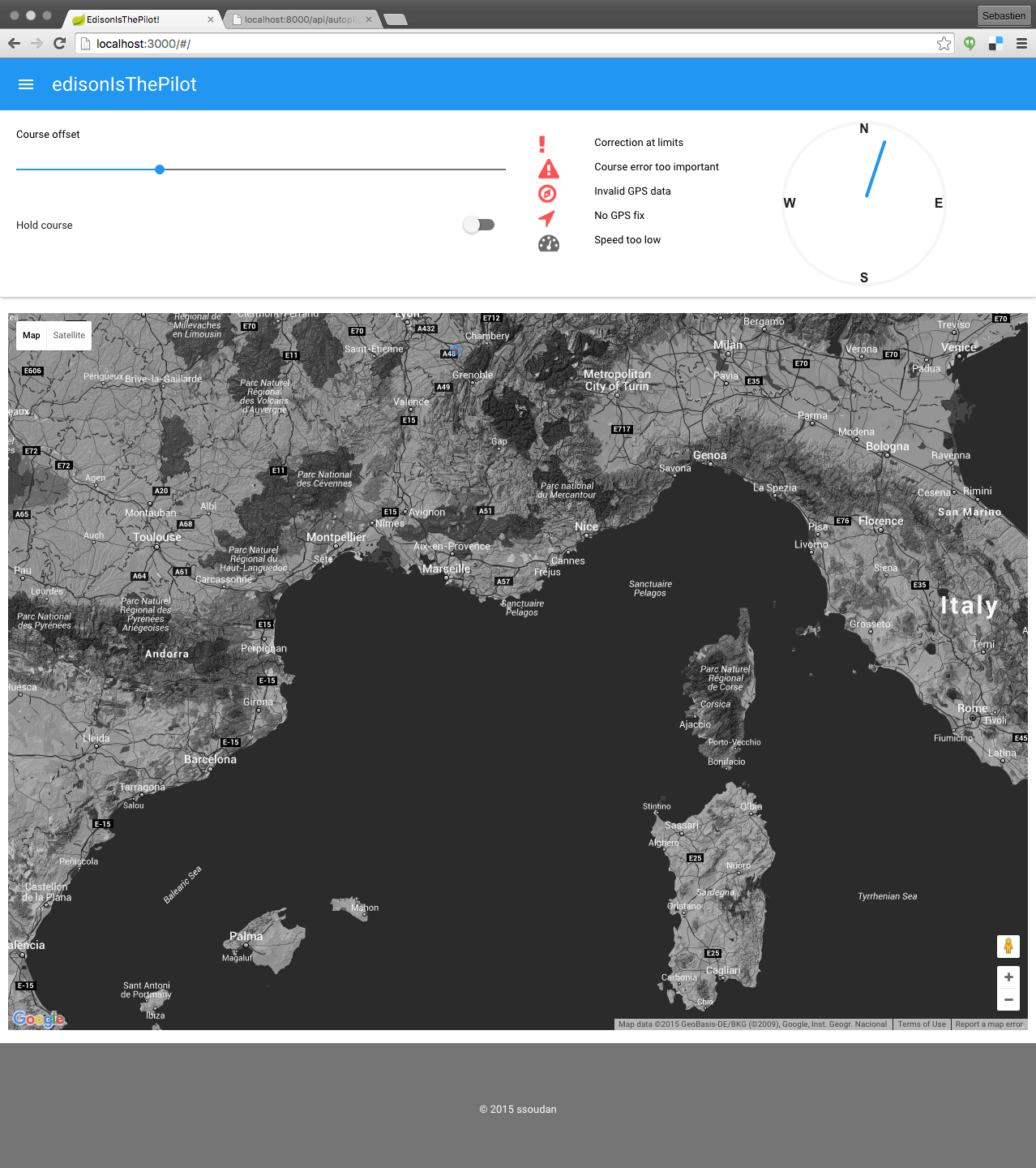
We have not covered all the code, in particular the UI part is not described here. In two words: the UI is in ReactJS, uses material-ui library for the UI components and is served by the autopilot program itself. Few REST endpoints are used to expose the warnings (LEDs status), the current course, the autopilot status. The UI can also modify the autopilot state via a PUT REST endpoint.
Next figure shows a screenshot of the UI:
Tuning
Once we have a running software, we are not yet done. This software will execute a infinite acquisition-control loop that need to be tune to our boat. Since we have a closed-loop control system, one of key points to achieve our goal of having an autopilot is its tuning as it both deals with the stability and the performance of the system.
We won’t focus too much on the performances (settling time, overshoot, null steady-state error…) and address the stability.
For the tuning, we use a tool we have developped named systemCalibration. This tools is used to collect the impulse response of the stepper motor + steering wheel + boat system. At time 0, we generate an impulse of control which result in the rotation of the steering wheel to a certain position. We then record the course of the boat as time goes. This is an open-loop test.
The following figure shows the impulse response for a particular setting.
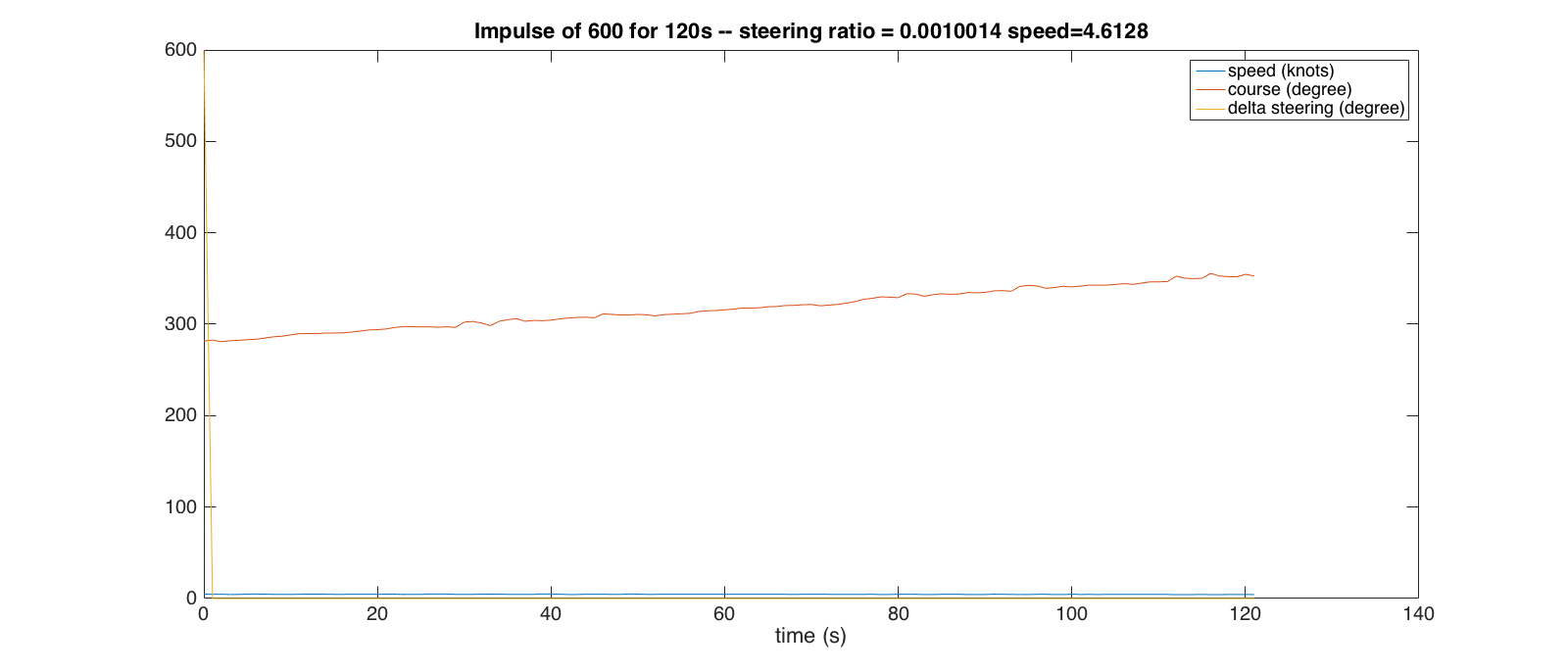
We can observe the recorded reponse is linear which validates our assumption that the boat system is a double integrator – impulse → integration → step → integration → linear ramp. From this record, we derive what we call the steering ratio – the slope of the ramp normalized by the impulse value:
\[ steeringRatio = \frac{steeringSpeed}{impulse} \]
where \(steeringSpeed\) is the slope of the course curve with respect to time (in degree per seconds) and \(impulse\) is the value of the control impulse (in degree). This constant is numerator of the transfer function of the system composed of the stepper motor, the steering wheel and the boat.
In Laplace domain, this transfer function is: \[ tf_{Boat}(s) = \frac{steeringRatio}{s^2}\]
We tested at different speed and started from different steering wheel position and this resulted in this figure:
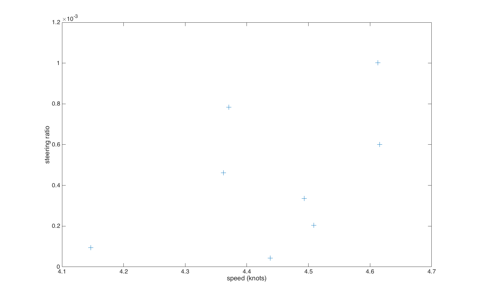 Values are spread over one order of magnitude! There is a bit of dispertion and much more testing is required. Philixxx will do that next week.
So now, to tune this system and be relatively safe, we will pick \(0.6 * 10^{-3}\), tune the system for this value, and verify it is stable for the extreme values: \(10^{-4}\) and \(10^{-3}\).
For the actual tuning, we used Matlab Simulink Control Design toolbox. The PID is a discrete PID with derivative filtering of which the z-transform expression is:
\[ tf_{PID}(z) = P + I \cdot T_s \cdot \frac{1}{z-1} + D \cdot \frac{N}{1 + N \cdot T_s \cdot \frac{1}{z-1}} \]
The tuning is a matter of defining a reasonable convergence speed without too much overshoot. But the main criteria we are after is the stability of the whole system. In few words, and just to introduce the gain and phase margins, the transfer function of the closed-loop system – from the set point to the actual course – has for denomimator the one plus the open-loop transfer function. To avoid instability, we need to avoid the case were the denominator is 0 and thus when the open-loop transfer function is -1.
To do so, we look at the Bode diagram of the aforementioned open-loop transfer function which is made of two diagrams: the gain as a function of the frequency and the phase as a function of the frequency. For an example of Bode diagram, see next figure. Since we want to stay as far as possible from -1 point, in this diagram we want to avoid the \((0dB, -180°)\) point. We define the gain margin as the minimal absolute gain (in dB) when the phase is -180° and the phase gain as the minimal absolute phase when the gain is 0dB.
Now to tune our system and verify the stability, we do the following:
- We set the \(steeringRatio\) value to the intermediate value,
- tune the PID with the tuning feature of the toolbox,
- note the phase and gain margins.
- Then we change the value of \(steeringRatio\) to one extreme value,
- get the margins from the tuning widget without changing the parameters of the PID.
- Finally we repeat this the other extreme value.
Next figure is the Bode plot of the open-loop system for the choosen PID parameters at \(steeringRatio=0.6 * 10^{-3}\). We can observe the phase and gain margin for this case.
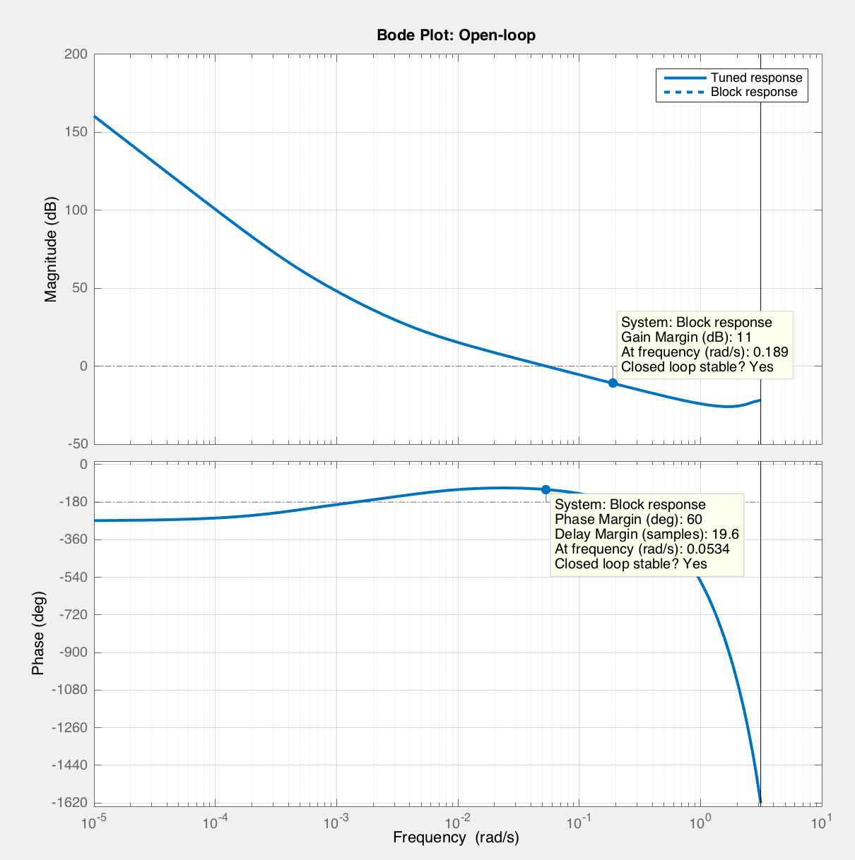
We got a 11dB gain margin (GM) and 60° phase margin (PM) at \(steeringRatio=0.6 * 10^{-3}\), a 6.54dB GM and 45.4° PM at \(steeringRatio=10^{-3}\) and a -26.4dB GM and 64° PM at \(steeringRatio=10^{-4}\).
We never get too close to the evil -1 point. The real system is supposed to be stable – real \(steeringRatio\) might be out of the range we have tested, the linearity of the overall system is assumed to be given, … Our PID parameters are the following:
- \(P=0.416293674251716\),
- \(I=0.000175132380116266\),
- \(D=88.5903379257174\),
- \(N=1.50633473583201\),
- with \(T_s=1\) since the GPS gives us one sample per second.
These parameters are very dependent on the mechanical coupling of the stepper motor and steering wheel as well as on the boat itself. The PID need to be tuned for each boat. A feature for a future version of this project could be the autotuning. This would make few runs with something similar to systemCalibration command, and automatically replicate the procedure described in this section to find acceptable parameters that lead to a stable closed-loop system.
Conclusion
Was a fun project to carry out. We have not covered all the features of this project: it has a Sine/Cosine output interface to feed the course signal to existing autopilot that use this sort of interface for the heading input, the UI shows the last 500 – configurable – points on the map, and you can add an offset to the setpoint via the UI to change a bit the target course. The code is open source (Apache License) and on github. Feel free to …
If you happen to use this on a real boat and crash it, well, that’s too bad because this code and post is served without any warranty.
BTW thanks to MathWorks for the ‘home’ edition of Matlab. Thanks to Intel for the Edison too. Love this tiny yet powerful platform.
Have fun! and remember: the sky’s the limit
Philippe (the captain) & Sebastien (the engineer)
